
THE VERTICAL BANQUET CAMERA PROJECT
by
J.B. Harlin
Originally Published in the September/October 2005 Issue of View Camera Magazine.
by Susan Harlin
Why would anyone want to undertake a complex project like building a wooden view camera? My answer would have to be, sometimes you come to a point where you just do whatever is necessary. There are those times you just have to take matters into your own hands.
We are a husband and wife photographic team. We travel, photograph and work together. Our specialty is black & white large, and ultra large, format photography. We work with film sizes from 4×5 to 16×20. Combined we have over fifty years of photographic experience. As artists we continually grow and expand our creativity. We have both undergone major changes in our working habits in the past few years. We have migrated to larger film. . . we mix our own developers. . . we enlarge less and make more contact prints. This, I feel, is a conscious choice of working habits and follows a natural evolution in the exploration of the medium of photography.
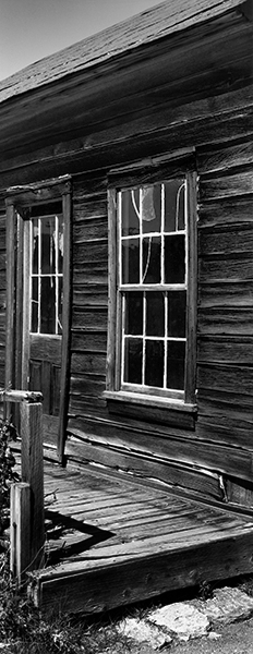
Over the past two years my wife has been experimenting with both 4×10 and 8×20 Banquet Cameras. She has produced some really nice photographs using these cameras and was wanting to expand the creative possibilities by shooting vertically. She first explored this elongated vertical format by rotating her 4×10 field camera on its tripod head. Not exactly easy to operate the camera in this position, but it did prove to be an interesting format that she wanted to further explore.
Her horizontal 4×10 is an off-the-shelf 4×5 wooden field camera with a 4×10 conversion back. The manufacturer offers a conversion back that consists of the rear focus rack, 4×10 rear frame with associated hardware, film back and bellows. To convert the camera you swap the backs. Not a bad idea, but it does have some shortcomings.
Her first truly vertical 4×10 camera was constructed by modifying the 4×5 back from the original factory camera. I removed the 4×5 rear box from the rear mounting hardware and fabricated a 4×10 box to replace it. Since she had a horizontal 4×10, all she had to do to convert to vertical was; roll the horizontal 4×10 back out of the bed; install the vertical back onto the bed; then move the film back and bellows to the vertical back. Simple and easy. . . well almost.
There were several inherent problems with this system. First, you had to swap a lot of hardware. Not always easy in the field, and it is time consuming. Not the best way of getting from horizontal to vertical, but certainly workable. Second there is a mechanical problem with this design. The camera is a converted 4×5 and lacks enough front rise to place the lens in the center of the vertical back. Working in the vertical mode, you almost always need some front rise for framing. The obvious fix would be to make the front standard longer. But if the front standard is made longer, then the camera would not fold. What is needed is a camera with a longer bed.
Having proven the validity of the vertical format, we set off to explore the options available to design and build a truly vertical banquet camera. Knowing there were no manufacturers that offered a design that met our exact needs, we knew we were looking at a totally custom piece of photographic equipment. Several factors came into play at this point. First, the cost of a totally custom camera. Next, the time it would take for delivery. Susan wanted the vertical 4×10 for an upcoming trip. . . and. . . I didn’t mention, she also wanted a vertical 8×20!
In order to meet the deadline we had created, and to keep our sanity, the only logical solution was to build the cameras myself. I am not a master tool and die maker, but I am a decent machinist and have some experience with wood working. I already had a lathe and vertical mill, but the workshop lacked a few key wood working tools. With the addition of a few new pieces of precision wood working equipment, the shop was upgraded and I was ready to begin.
At this point let me say that this is not an easy project. You are not going to build a camera like this with a few hand tools. If you are a serious photographer, you are better off spending your energy making photographs. This was something that my wife and I undertook as part of a larger photographic project. Don’t even try this unless you are really sure of your abilities.
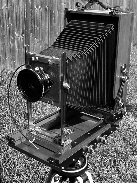
Having made the commitment to build two cameras from scratch, where do you begin? You start with an initial concept. The idea was to design the vertical camera exactly like the horizontal. This would be a complete camera, only requiring a lens to make an image. The main difference would be the bed, which would be the same length as the vertical back, and the front standard would have generous rise. With the longer bed, the camera will fold just like any field camera for easy transportation.
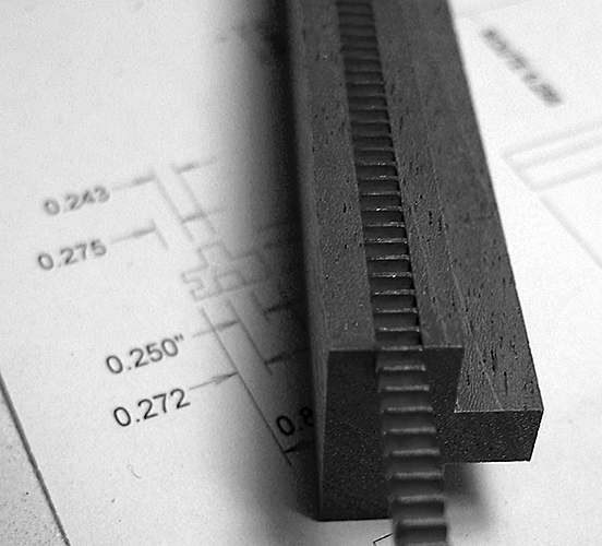
I disassembled the factory horizontal camera, made measurements, then created drawings of the necessary piece parts. Some drawings were done using computer CAD software, others were just sketches in a notebook. Numerous parts for the new camera were resized and the necessary changes were made to the drawings. Once I felt I had a stable design with enough drawings and notes, the process of fabricating the parts began.
We ordered rough cut mahogany along with brass and aluminum stock. At this point it was just a matter of fabrication, fitting, finishing and assembly.
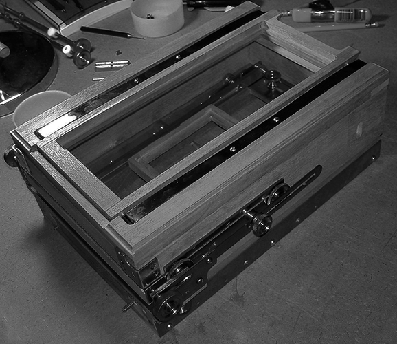
The various wooden and brass piece parts that make up the camera were fabricated and assembled as the camera was built up starting with the main base. The front and rear focus beds were fabricated and then mated with the base. Rack and pinion drive is used for the front and rear focus of the camera. Next the rear box is built up from raw wood, then attached to the rear standard hardware and mated with the rear focus bed. The film back is constructed, machined for the ground glass and attached to the rear box. Last the wooden front standard along with the front and rear bellows frames are fabricated. Then the front standards are machined and fitted to the front focus bed.
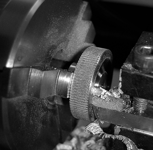
All of the associated hardware, knobs, brackets, axles, braces and metal sliding components are machined from brass stock and checked for proper fit. The ground glass springs are formed from spring steel. There are about 150 individual pieces made from wood and brass that had to be hand made and fitted. Custom fixtures had to be machined in order to make some of the more intricate parts. Brackets were first worked to the proper shape, machined with holes and slots, then formed on a metal brake.
At this point the entire camera frame is assembled and checked for proper fit. Next the component pieces are disassembled and prepared for finishing. The wooden parts are fine sanded and given 2-3 coats of gloss varnish. The brass hardware is polished, cleaned, then hand lacquered. Next comes final assembly. This is the final fit and adjustment of the body of the camera.
Note that the rear standard hardware on the vertical 4×10 was scavenged from the original 4×5 back from the factory camera. This was done to expedite the project since we were on a deadline. With the exception of these rear standard brass parts, every piece of the camera was fabricated and assembled in my shop.
Next the bellows is constructed. I learned how to build bellows on another project. The materials are difficult to find. We had previously located a supply of vulcanized nylon material and bought all the distributor had in stock. I don’t have a clue as to where you can find more. The construction of a camera bellows is an art unto itself and I learned by trial and error. It took about three days to build the complete bellows for the vertical 4×10 camera.
At this point the only thing left is the ground glass. I grind my own glass for all of our view cameras using aluminum oxide grinding compound that is used to grind mirrors for telescopes. A 4×10 ground glass takes about two hours to complete.
This completes the vertical 4×10 camera. All that is left to do is apply a coat of hand-rubbed micro-crystalline wax, followed by a real-world test using film. The first tests are performed on a sunny day in the back yard. We shoot several holders of film, mainly to check for major light leaks and to be sure the hardware all fits as it should. The camera is now ready for the road.
The 4×10 vertical camera has worked out very well. My wife has made numerous images with this camera and she is very satisfied with how it handles in the field. The finished camera measures 10″x12.5″x4.75″ and weighs 8.4lbs. It is easily backpacked along with six film holders and two lenses. The entire project took 2 months and approximately 280 hours to complete.
This is the first camera I have built completely from raw materials. It has been a test bed for learning exactly how to construct a working wooden field camera. In part two of this article we will take a look at the vertical 8×20 project.
For more information and to view the photography of J.B. and Susan Harlin, visit their web site; www.jbhphoto.com