CONSTRUCTION OF THE 8X20 VERTICAL CAMERA
ASSEMBLY, BELLOWS & GROUND GLASS
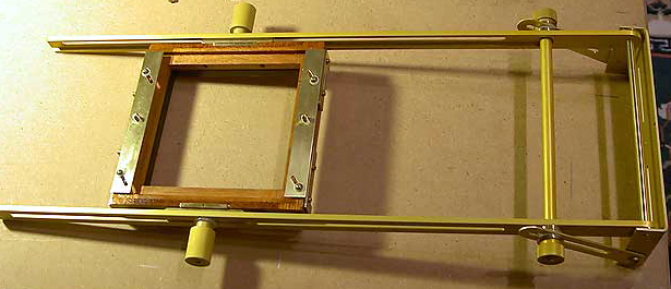
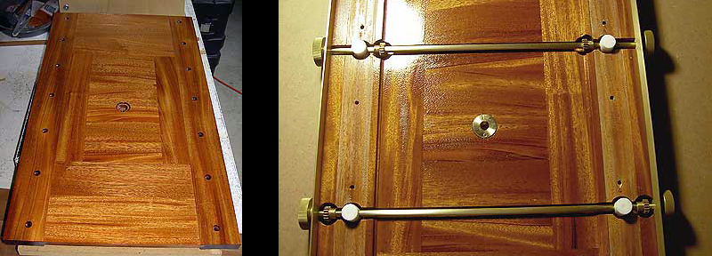 Once it is determined that all of the parts fit and everything works, it is time to completely disassemble everything and finish the parts. The aluminum is gold anodized. The brass is lacquered. The wooden parts are given 2-3 coats of clear gloss varnish. Once everything is dry it is time to begin assembly. Above is the camera base after finishing (left photo). First the front and rear drive mechanism is installed. The white objects on the axles are the Teflon focus dampers (right photo).
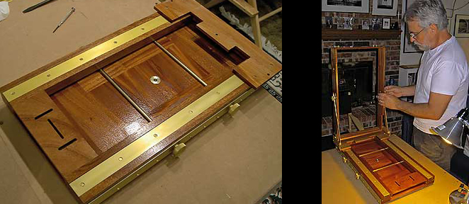
Next the front and rear focus sliders are installed and mated to their gear drive. Then the rear standard box and hardware are installed.
The rear standard box folded.
The front standard assembly.
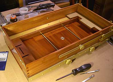
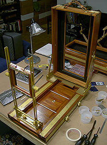 Here is the entire camera body fully assembled.
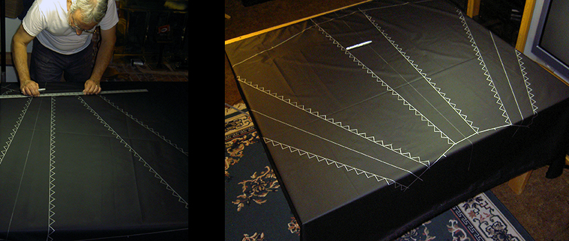
Bellows construction begins with the lay out of the pattern on the bellows material. Since we had previously built an 8×20 bellows, the patterns were already designed and confirmed. This size bellows requires a piece of material approximately 48×70 inches.
Once the pattern is laid out, card stock ribs are cut to fit and glued into place on the bellows material. There are 224 ribs in this bellows. The bellows fourth side is seamed together and glued. Once all of the ribs are glued, a black fabric inner liner is glued over the ribs. . . the bellows is built inside out.
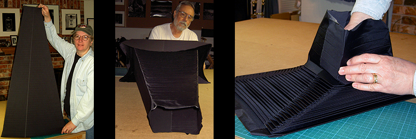
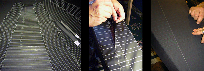
The bellows is now fully assembled (first photo). Next the assembly is turned through itself. The small end is fed through the large end (center photo). Then the bellows is folded to its final shape (last photo).
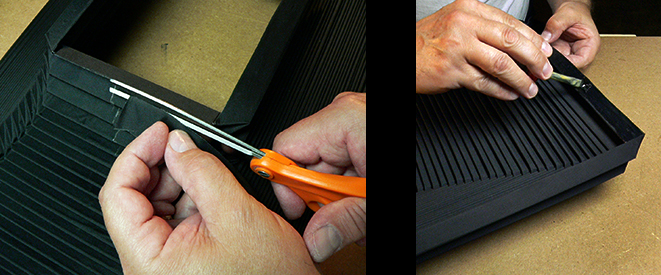
The excess material is trimmed and the fit to the wooden frames is confirmed. Then glue is applied to the end of the bellows and the frames.
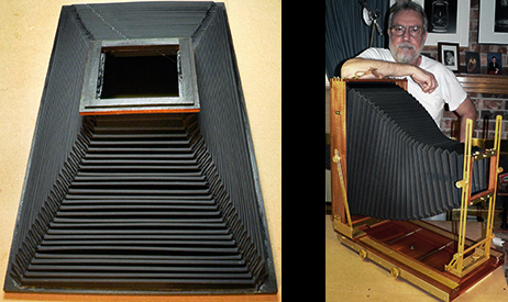
Here is the fully assembled bellows. . . and the camera with the bellows installed for the first test fit.
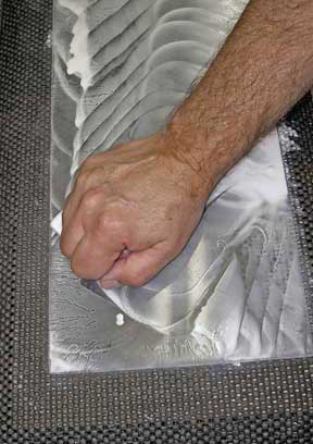
The glass has been cut to size and is being hand-ground using aluminum oxide.
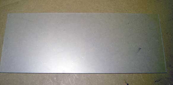 The finished ground glass ready for installation.